- 您现在的位置:买卖IC网 > Sheet目录409 > DR-TRC105-450-EV (RFM)BOARD EVALUATION 450MHZ RFM RFIC
�� �
�
�Figure� 9�
�Note� that� start� pattern� detection� is� enabled� only� if� data� and� clock� recovery� is� enabled.�
�3.4� RSSI�
�The� received� signal� strength� is� measured� in� the� amplifier� chains� behind� the� second� mixers.� Each� amplifier� chain�
�is� composed� of� 11� amplifiers� each� having� a� gain� of� 6� dB� and� an� intermediate� output� at� 3� dB.� By� monitoring� the�
�two� outputs� of� each� stage,� an� estimation� of� the� signal� strength� with� a� resolution� of� 3� dB� and� a� dynamic� range� of�
�63� dB� is� obtained.� This� estimation� is� performed� 16� times� over� a� period� of� the� I� and� Q� signals� and� the� 16� samples�
�are� averaged� to� obtain� a� final� RSSI� value� with� a� 0.5� dB� step.� The� period� of� the� I� and� Q� signal� is� the� inverse� of� the�
�deviation� frequency,� which� is� the� low-IF� frequency� in� OOK� mode.� The� RSSI� effective� dynamic� range� can� be� in-�
�creased� to� 70� dB� by� adjusting� MCFG01_IF_Gain[1..0]� for� less� gain� on� high� signal� levels.�
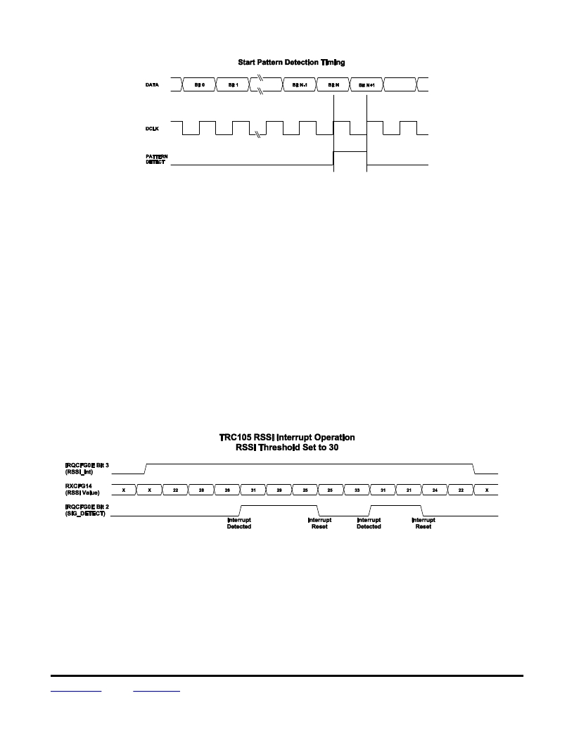
�The� RSSI� block� can� also� be� used� in� interrupt� mode� by� setting� the� bit� IRQCFG0E_RSSI_Int[3]� to� 1.� When�
�RXCFG14_RSSI� is� equal� or� greater� than� a� predefined� value� stored� in� IRQCFG0F_RSSI_thld� ,� bit� IRQCFG0E_�
�SIG_DETECT[2]� goes� high� and� an� interrupt� signal� RSSI_IRQ� is� generated� on� pin� IRQ0� if� IRQCFG0D_RX_�
�IRQ0[7..6]� is� set� to� 01� (see� Table� 10).� The� interrupt� is� cleared� by� writing� a� 1� to� bit� IRQCFG0E_� SIG_DETECT[2]� .�
�If� the� bit� RSSI_IRQ� remains� high,� the� process� starts� again.� Figure� 10� shows� the� timing� diagram� of� RSSI� in� inter-�
�rupt� mode.�
�Figure� 10�
�3.5� Receiving� in� Buffered� Data� Mode�
�The� receiver� works� in� Buffered� data� mode� when� the� MCFG01_Mode[7..6]� bits� are� set� to� 01.� In� this� mode,� the�
�output� of� the� data� and� clock� recovery,� i.e.,� the� demodulated� and� resynchronized� signal� and� the� clock� signal� DCLK�
�are� not� sent� directly� to� the� output� pins� DATA� and� IRQ1� (DCLK).� These� signals� are� used� to� store� the� demodulated�
�data� in� blocks� of� 8� bits� in� a� 64-byte� FIFO.� Figure� 11� shows� the� receiver� chain� in� this� mode.� The� FSK� and� OOK�
�demodulators,� data� and� clock� recovery� circuit� and� start� pattern� detect� block� work� as� described� for� Continuous�
�data� mode,� but� they� are� used� with� two� additional� blocks,� the� FIFO� and� SPI.�
�www.RFM.com� E-mail:� info@rfm.com�
�?� 2009-2013� by� RF� Monolithics,� Inc.�
�Technical� support� +1.800.704.6079�
�Page� 15� of� 67�
�TRC105� -� 05/29/13�
�发布紧急采购,3分钟左右您将得到回复。
相关PDF资料
DR-TXC100-433
BOARD EVALUATION 433MHZ TXC100
DR-WLS1273L-EV
KIT EVAL FOR WLS1273L
DR7000-DK
3G DEVELOPMENT KIT 433.92MHZ
DR7001-DK
3G DEVELOPMENT KIT 315 MHZ
DR7003-DK
3G DEVELOPMENT KIT 303.825 MHZ
DR8000-DK
3G DEVELOPMENT KIT 916MHZ
DR8001-DK
3G DEVELOPMENT KIT 868.35MHZ
DR8100-DK
3G DEVELOPMENT KIT 916MHZ
相关代理商/技术参数
DRTU06D06
功能描述:时间延迟和计时继电器 180-240VAC/DC 1-60VDC 6A
RoHS:否 制造商:Crydom 显示器类型:Hand Dial 电源电压:280 VAC 定时范围: 触点形式: 触点额定值:6 A 端接类型:DIN Rail
DRTU24A06
功能描述:时间延迟和计时继电器 180-240VAC/DC 24-280VAC 6A
RoHS:否 制造商:Crydom 显示器类型:Hand Dial 电源电压:280 VAC 定时范围: 触点形式: 触点额定值:6 A 端接类型:DIN Rail
DRTU24A06R
功能描述:时间延迟和计时继电器 90-140VAC/DC 24-280VAC 6A
RoHS:否 制造商:Crydom 显示器类型:Hand Dial 电源电压:280 VAC 定时范围: 触点形式: 触点额定值:6 A 端接类型:DIN Rail
DRTU24B06
功能描述:时间延迟和计时继电器 90-140VAC/DC 24-280VAC 6A
RoHS:否 制造商:Crydom 显示器类型:Hand Dial 电源电压:280 VAC 定时范围: 触点形式: 触点额定值:6 A 端接类型:DIN Rail
DRTU24B06R
功能描述:时间延迟和计时继电器 2-24VAC/DC 24-280VAC 6A
RoHS:否 制造商:Crydom 显示器类型:Hand Dial 电源电压:280 VAC 定时范围: 触点形式: 触点额定值:6 A 端接类型:DIN Rail
DRTU24D06
功能描述:时间延迟和计时继电器 12-24VAC/DC 24-280VAC 6A
RoHS:否 制造商:Crydom 显示器类型:Hand Dial 电源电压:280 VAC 定时范围: 触点形式: 触点额定值:6 A 端接类型:DIN Rail
DRTU24D06R
制造商:Crydom 功能描述:Relay; SSR; Muti Func;12-24VAC/DC; 24-280VAC ; 6A 制造商:Crydom 功能描述:RELAY SSR 6A LONG TIME DELAY 制造商:Crydom 功能描述:SSR, TIME DELAY, 6A, 280VAC, DIN RAIL; Operating Voltage Min:24VAC; Operating Voltage Max:280VAC; Control Voltage AC Min:12VAC; Control Voltage AC Max:24VAC; Control Voltage DC Max:24VDC; Timer Functions:Multifunction ;RoHS Compliant: Yes 制造商:Crydom 功能描述:DRTU24D06R/Muti Func,12-24VAC/DC, 24-280VAC 6A / ROHS: Y
DRTX06D06
制造商:CRYDOM 制造商全称:Crydom Inc., 功能描述:6 Amp AC and DC Rated output